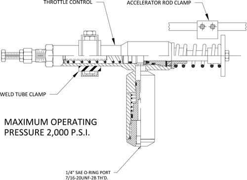
Hydraulic Throttle Controls

Design Features
- Automatically cycles engine-pump to predetermined R.P.M.
- Allows single throttle control for multi-pump systems.
- Fuel economy – Increased idle time.
- Reduce engine and pump wear
- Sense all four (4) pressure levels.
- Give repeatable work cycle time.
- Accelerates operator training and daily efficiency.
Operation
This device is designed to work in conjunction with open centered hydraulic systems powered by internal combustion engines and is adaptable to most hydraulically actuated machinery such as aerial lifts, cranes, and boom type loaders.
The actuator operates in such a manner as to bring the engine driven pump up to a predetermined R.P.M. by controlling the engine throttle during work demand cycles. The engine is allowed to return to idle when control valve is in center position.
The throttle control is capable of sensing four (4) levels of fluid pressure as found in hydraulic systems:
Level 1: Back pressure caused by restrictions in the fluid passages with the engine at idle speed and valving in the centered position.
Level 2: Back pressure caused by restrictions in the fluid passages with the engine at full operating speed and valving in the center position. (Occurs at the end of operating cycle)
Level 3: System pressure with the valving in operative cycle requiring the least amount of fluid pressure. (Such as lowering outriggers)
Level 4: System pressure while operating through that part of the work cycle requiring the most in system pressure.
If pressures in level 2 are higher than level 3, part of the efficiency of the throttle control may not be realized. The spring must be set to overcome pressure of level 2.
See Installation/Adjustments Page for More Information
| PART NO. FOR ORDERING | |
|---|---|
| Item | Part No. |
| Throttle Control | 2145 |
| Repair Kit for Control | 2145-14 |
| Shuttle Valve | 2114 |
Maximum Operating Pressure: 2,000 P.S.I.