Safety Information for 5TV, 6TV, and TVF Couplings
General Instructions
Scope
This safety bulletin is to warn against improper selection, installation, use, etc. of Hydraulics, Inc. coupling products in fluid power system.
Distribution
A copy of this safety information should be provided to all persons that are responsible for selecting, applying and using these couplings. Do not attempt to select or use these products without clearly understanding this guide and the definitions and instructions provided by this specific Hydraulics, Inc. publication.
Fail Safe
It is possible for a coupling, coupler, nipple, or its attached fluid conductors to fail without warning for a number of reasons. Design all systems and equipment for fail-safe operation such that failure of coupling, fluid conductor or other component will not endanger persons or damage property.
User Responsibility
Due to the differences in operating conditions of fluid power systems, Hydraulics, Inc. and its distributors do not represent or warrant that any thread to connect coupling is adequate for any particular fluid power system use. Therefore, it is the users’ sole responsibility for reading and following this safety bulletin and other Hydraulics, Inc. catalogs and any other documents pertaining to use. Also, through its own analysis and testing, the user must determine if the coupler meets the use requirements and does not present a health or safety hazard.
Selection of Hydraulics, Inc. Couplings
These thread to connect couplings are offered in 3 basic product categories. When planning a fluid system plumbing, it is suggested all types of couplings be considered. Port size, port connector, valve type, operating pressure, fluid velocity and volume should all be considered when selecting the appropriate coupling. Also consider, when couplings, couplers, nipples, and their associated fluid conductors are in final assembly, the working pressure range for the assembly does not exceed the lowest pressure rated component in the assembly. Relative to the 5TV and 6TV Series couplings, the pressure rating of an un-coupled assembly is lower than that of a coupled assembly. See coupling performance info.
Temperature Range of Equipment and Fluid
Fluid and ambient temperatures determine coupling seal type required. Should fluid temperature exceed the standard (Buna-N) seal temperature rating of (-30° to 250°F // -34° to 121°C), seal deterioration will likely result in fluid leakage. Transient temperatures also have potential for damaging seals, especially at system shutdown. High temperatures can also damage protective plating and precipitate corrosion.
Fluid Compatibility
Composition of the coupling carbon steel body, Buna-N seals and Teflon ™ seal back-up rings must be compatible to the fluid systems environment. Other materials may be required.
Pressure Drop
Pressure drop or differential pressure is the loss of pressure between any two points in a fluid system. Measured as a loss in pounds per square inch, it is the resistance to fluid flow through a component based on a given volume. Refer to flow data.
Pressure Limitations
Coupling rated operating pressure gives acceptable margin for safety. System designers should assure systems pressure does not exceed this rating. Additional thought should be given to pressure of fluid trapped behind valves of disconnected coupling halves. Fluid pressures increase from effect of thermal expansion in associated conductors and increases the torque needed to assemble the coupling halves. Should valves of both halves be of this condition at assembly, the valve presenting the lower of the two pressures will open first. As threaded assembly progresses, the first valve that opens will seat into its poppet guide to then drive the second valve open. Under extreme pressure the force required to open the second valve can exceed available torque. For this reason the poppet guides are of high strength material. See maximum connect under pressure listed in coupling performance info.
Thread To Connect
For purpose of safety to operators and environment, partial assembly thread make-up occurs before assembly seal engagement. The two valves begin opening following seal engagement. Full valve opening results with full thread make-up.
The reverse of this sequence occurs at disassembly. Should valves fail to seat as indicated by presence of excess fluid upon assembly seal disengagement, the remaining thread make-up allows seal re-engagement until assessment is made for controlling fluid spill.
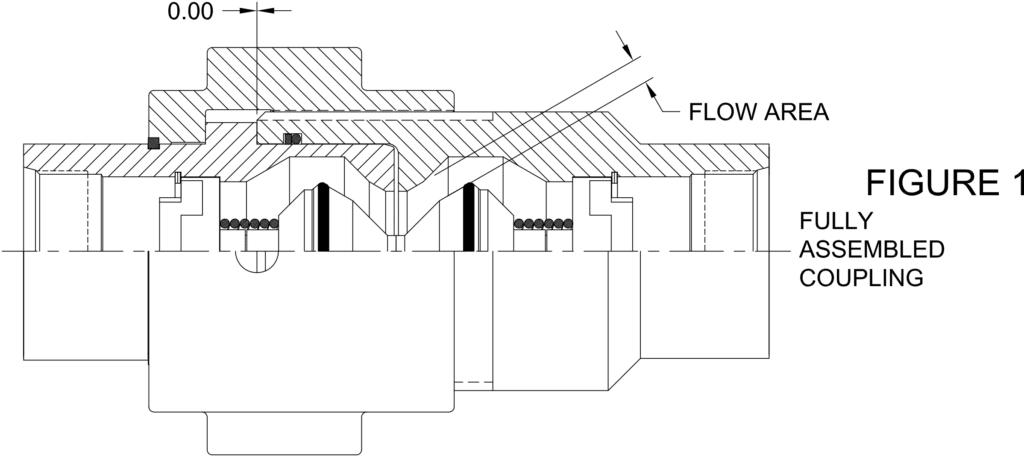
Less than full assembly of the coupler and nipple assemblies will have a detrimental effect on coupling performance and possibly the associated components. In a fully assembled coupling, the valves are restricted by the valve guides to a few thousand’s inch of axial movement. Refer to Figure 1. Note the large fluid flow area this condition provides.
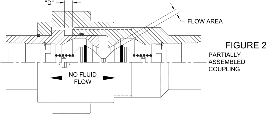
If the coupling is left unassembled by a distance “D”, then the valves are free to shift axially by the same amount “D”. Refer to Figure 2. Under no fluid flow conditions, the valves will self-center due to the equal but opposite spring forces. Note that the fluid flow area is reduced in the condition.
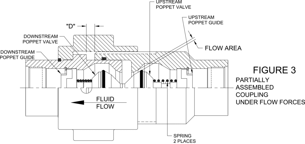
In a partially assembled coupling with sufficient flow forces, the valves ill shift downstream and come to rest on the downstream valve guide. This causes the upstream valve to approach its’ seat. Refer to Figure 3. Note the drastically reduced fluid flow area in this condition. As distance “D” approaches that necessary to close the upstream valve, the pressure drop across that valve will become excessive. This pressure drop results in significant forces being generated which are imparted to the downstream valve guide. Under the right conditions, these forces can cause mechanical damage up to and including failure of the downstream valve guide.
To help assure this condition does not exist, the coupler nuts contain an inspection hole for visual confirmation by the operator of full assembly.
Corrosion Resistance
Couplings are produced from carbon steel and receive an exterior coating of zinc plating with a yellow chromate RoHS compliant finish. Goth fluid media and system operating environment should be considered if corrosion is a factor.
Welding & Brazing
Heating plated couplings, couplers, nipples, and port adaptors above 250°F (121°C) as in welding, brazing etc., may result in seal and plating damage resulting in fluid loss and/or corrosion.